KCF Guide Pins Explained: Function, Insulation Layer, Service Life & Maintenance

KCF Guide Pins Explained: Function, Insulation Layer, Service Life & Maintenance
A KCF guide pin is one of those parts that does its whole job invisibly — when it works, nobody on the line thinks about it, and when it fails, everybody does. This article is about the pin as a component: what it actually does inside a welding station, how its insulation layer governs its behavior, when it should be replaced, and how to install and maintain it so it reaches the full service life it is capable of delivering.
We are not going to re-explain the KCF material itself here — if you want the metallurgy of the insulating alloy, our article on what KCF alloy is covers that, and if you are weighing the pin against a ceramic alternative, our KCF versus ceramic guide pin comparison is the better starting point. This piece assumes you have already chosen KCF and now need to understand the part in your hand: how it works, how long it lasts, how to specify it, and how not to ruin it through avoidable handling mistakes.
What a KCF Guide Pin Does in a Welding Station
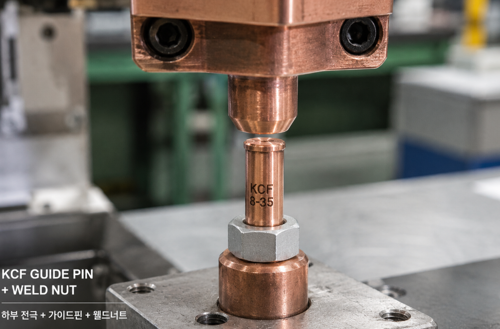
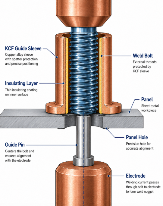
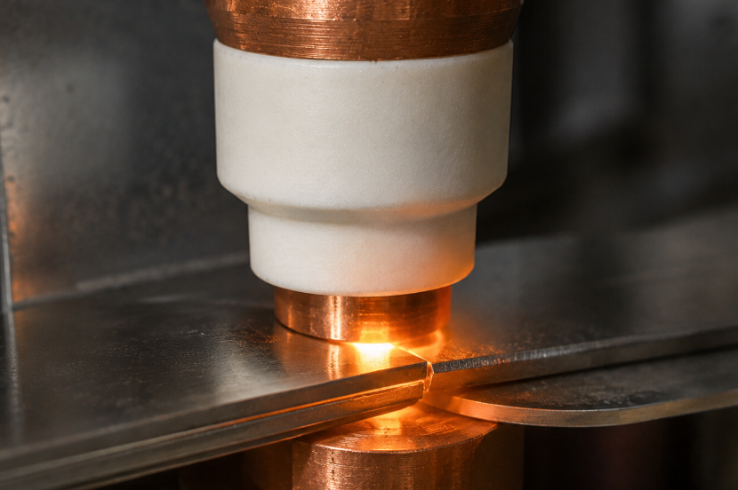
The core function of a KCF guide pin is positional: it locates a nut, bolt, or stud precisely over the intended weld point and holds that position while the electrodes close and the current fires — all without conducting that current itself. The pin is the reference that turns a loose fastener into a precisely placed one. In a typical nut welding setup, the pin protrudes from the lower electrode; the operator or an automatic feeder drops a weld nut over the pin, the nut self-centers on it, and the upper electrode descends to make the weld. This protruding, retractable-pin arrangement — a metal pin with a hard, wear-resistant surface that holds the nut during welding — is well established in the resistance welding patent literature on guide pins for nut welding.
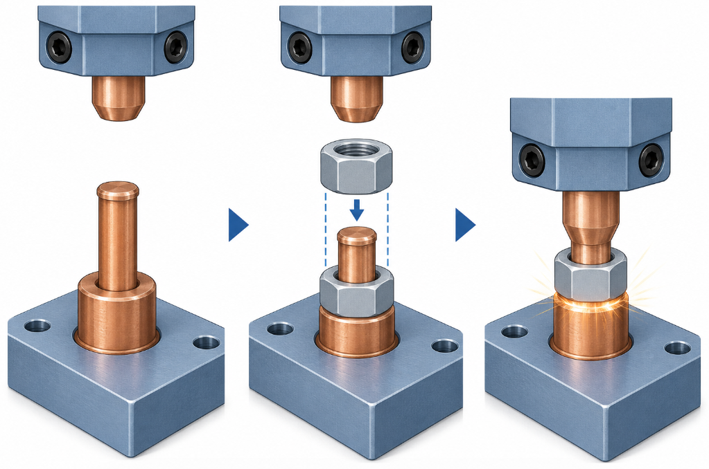
That single job — locate without conducting — is the entire reason the KCF guide pin exists as a specialized part rather than an ordinary metal dowel. An ordinary conductive pin in that position would shunt welding current through itself, starving the real joint and potentially welding the pin to the fastener. The insulating character of the KCF guide pin is what keeps the current where it belongs.
It helps to appreciate just how much rides on this small part’s accuracy. The weld nut or stud it positions becomes a permanent threaded mounting point on the finished product — a seat anchor, a bracket fixing, a hinge attachment. If the pin places that fastener even slightly off, every downstream assembly step that mates to it inherits the error: a bolt that will not start cleanly, a bracket that sits skewed, a panel gap that shows. The pin is therefore not just a welding aid but the first link in a dimensional chain that runs all the way to final assembly. That is why locating precision, not merely “holding the nut roughly in place,” is the property that defines a good guide pin, and why the loss of that precision is the most common reason one gets replaced.
Where KCF Guide Pins Are Actually Used
Across our customer base, KCF guide pins land in four main positions, in rough order of volume:
- Nut welding location — by far the most common. The pin centers a weld nut over the hole in the panel.
- Bolt and stud welding location — positioning a stud or bolt for projection or resistance welding.
- Projection welding location — holding the fastener aligned over its projections so they meet the panel evenly. In these systems the lower electrode carries the weld location pin through the panel opening before the fastener is placed, as detailed in patent literature on weld-nut locating systems, and accurate pin location is what keeps those projections meeting the panel squarely.
- Multi-fastener and complex-fixture location — several pins working together in one fixture to position a cluster of fasteners or an awkward geometry.
If your application is in this list, a KCF guide pin is doing exactly what it was designed for. The further your use drifts from “locate a fastener without conducting,” the more worth asking whether the pin is the right part at all.
How the Insulation Layer Defines a KCF Guide Pin’s Behavior
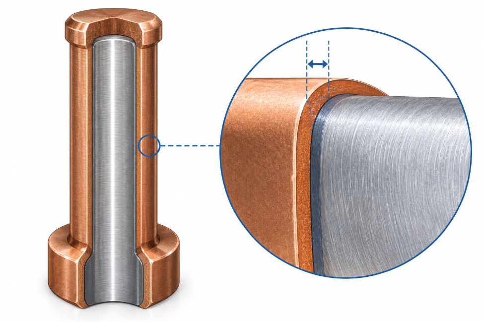
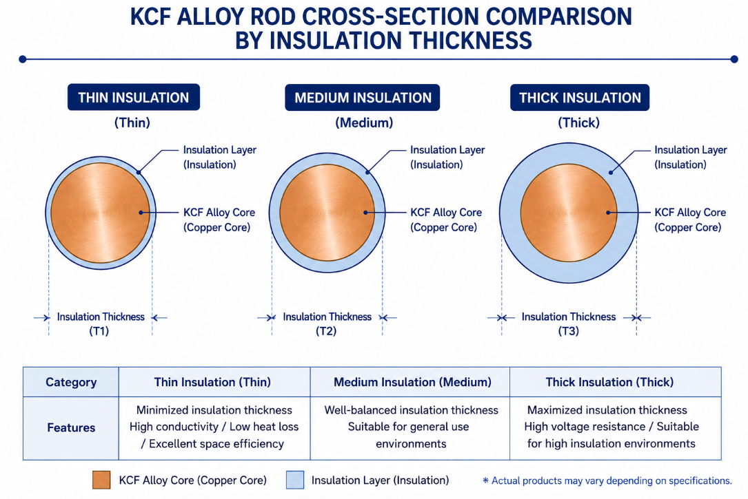
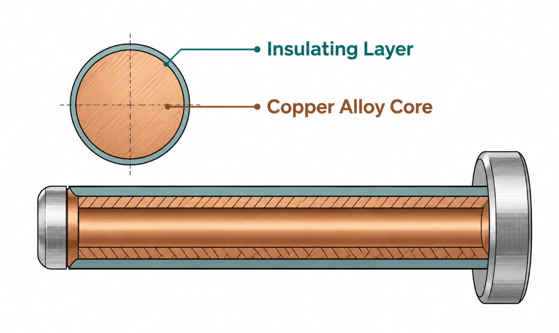
Everything distinctive about a KCF guide pin traces to its insulating surface layer. The pin has a tough body for mechanical strength and a hard insulating skin — on our pins typically in the 8–15 μm range — that provides the electrical isolation. We cover how that layer is formed in the material article; here, what matters is how the layer governs the pin’s day-to-day behavior as a working component.
Three practical consequences follow from the layer:
The layer is the functional surface, not a coating to ignore. A KCF guide pin works because its outer skin does not conduct. Treat the surface as the working part of the tool, because it is — not as a finish that can be scratched, filed, or pressed against hard objects without consequence.
Layer thickness is a performance choice. A thicker insulation layer generally withstands more wear before electrical isolation degrades, while the right thickness depends on the duty cycle and abrasion the pin will face. This is why we offer KCF guide pins in different insulation layer thicknesses rather than one default — matching the layer to the workload is part of specifying the pin correctly.
When the layer goes, the pin’s job is over. Unlike a wear part that gradually loses dimension but keeps functioning, a KCF guide pin whose insulation has worn or been breached has lost the one property that defined it. It may still look intact and still fit the fixture, but electrically it is no longer doing its job — which is exactly why service life for these pins is judged differently than for ordinary mechanical parts.
This last point has a subtle and important consequence for how you monitor the part: visual condition can lie. A worn cutting tool looks worn, a stretched belt looks loose — the damage announces itself. But a breached insulation layer can be invisible to the eye, a microscopic gouge or a thinned patch that no longer isolates current yet shows nothing obvious on inspection. This is why the most reliable end-of-life signal for these pins is often electrical or positional behavior on the line — stray current appearing, weld quality drifting, location slipping — rather than how the surface looks. A pin that “looks fine” is not the same as a pin that is fine, and lines that judge replacement purely by appearance tend to run pins past their real electrical end-of-life without realizing it. The practical defense, again, is planned replacement on a count rather than reliance on a visual check that the failure mode is specifically good at hiding from.
How to Judge a KCF Guide Pin’s Service Life
Here is the honest reality from our order data: most customers replace KCF guide pins reactively, when something goes wrong, rather than on a planned schedule. Understanding the failure signals helps, but the better practice — which a minority of well-run lines follow — is planned replacement before those signals appear. Let us cover both.
| Material Type | Est. Service Life (Welds) | Primary Failure Mode | Impact Resistance | Insulation Wear Rate |
| KCF Alloy (Guide Pins) | 30,000 – 50,000+ | Gradual surface skin wear | High (Tough alloy core) | Predictable / Gradual |
| Zirconia Ceramic | Highly Variable* | Catastrophic shattering | Low (Extremely brittle) | Zero wear (until broken) |
| Coated Steel | 10,000 – 20,000 | Coating flaking / Spalling | High | Rapid |
The Four Signals Customers Replace KCF Guide Pins On
In practice, customers pull a KCF guide pin when they hit one of four triggers:
- Positioning goes off — the pin no longer locates the fastener accurately, parts shift or the nut wobbles on the pin. Loss of locating precision is the most common practical trigger.
- Insulation fails — shunting or stray current appears, weld quality drops in a way that traces to current going where it should not. This is the electrical end-of-life.
- Visible wear or chipping — the pin shows obvious mechanical wear, a chipped edge, or surface damage serious enough to notice on inspection.
- Planned replacement — the well-run minority swap the pin on a weld-count or calendar schedule before any of the above appears.
The pattern worth noticing: the first three are all reactive — they mean the pin already caused a problem before it was replaced. Each one represents some scrap, some quality drift, or some downtime that planned replacement would have avoided.
Why Planned KCF Guide Pin Replacement Pays Off
| Replacement Approach | What It Costs You | Best For |
|---|---|---|
| Replace on positioning failure | Scrap and rework from mislocated welds before catch | Low-volume, low-stakes lines |
| Replace on insulation failure | Quality drift and possible bad welds shipped | Never ideal — electrical failure is hard to spot fast |
| Replace on visible wear | Inspection-dependent; variable timing | Lines with disciplined visual checks |
| Planned by weld count / cycle | A pin replaced slightly early | High-volume, quality-critical lines |
The economics mirror what we see with electrode caps: a part replaced slightly early on a schedule is far cheaper than the scrap, rework, and unplanned stops that a part replaced after it failed leaves behind. If your KCF guide pins sit in a high-volume automotive or appliance line, logging their life in weld counts and replacing on a schedule almost always wins. To set that schedule, you need a few cycles of real data: run pins to failure on a sample basis, record the weld counts, and set the planned interval comfortably below that figure.
How much below is a judgment worth making deliberately. Set the interval too close to the failure point and you save consumable cost but risk the occasional pin reaching end-of-life mid-shift — defeating the purpose. Set it too conservatively and you discard pins with useful life left. A common starting point is to plan replacement somewhere around 70–80% of the observed average life to failure, then refine as your own data accumulates. The exact fraction matters less than the discipline of having a number at all: a line replacing on a defined count, however imperfect, almost always outperforms a line replacing on “when it seems to be acting up,” because the first catches the pin before it makes scrap and the second catches it after.
A note on what shortens life prematurely: most of the cases where a KCF guide pin dies far earlier than expected are not the material wearing out — they are installation or maintenance mistakes that damaged the pin before it ever had a fair chance. That is the next section.
How to Install and Maintain a KCF Guide Pin Correctly
Because the insulation layer is the functional surface, installation and maintenance are where KCF guide pin life is most often won or lost. These are the mistakes we see most frequently from customers, each with its fix.
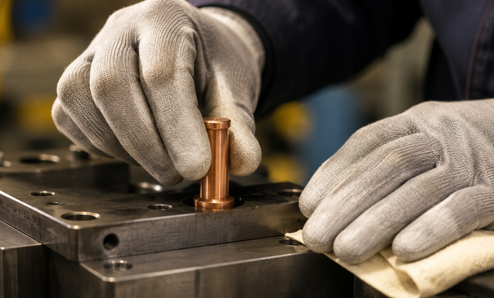
It is worth saying plainly why this section matters more than it might seem: in our experience, the gap between a pin that reaches its full rated life and one that fails in a fraction of it is more often a handling difference than a product difference. Two identical pins from the same batch, installed on two lines, can show wildly different lives purely because one line seats them gently and cleans them carefully while the other forces them in and scrapes them with whatever is to hand. That is encouraging, because it means most premature-failure problems are fixable for free — not by buying a better pin, but by changing how the existing pin is treated. The mistakes below are common precisely because each one feels harmless in the moment; their cost only shows up cycles later as a pin that died young.
Installation Mistakes That Kill KCF Guide Pins Early
Pressing in too hard and damaging the insulation layer. Forcing a pin into its seat with excessive force can crush or breach the insulation skin at the contact points. The pin goes in looking fine but starts compromised. Seat the pin with appropriate force, not brute force.
Wrong size or tolerance for the fixture. A pin whose diameter or tolerance does not match the fixture either sits loose (poor location, premature wobble) or requires forcing (insulation damage on install). This is why getting the size and tolerance right against the actual fixture matters before the order, not after.
Poor hole alignment and coaxiality causing uneven wear. If the pin’s seat and the mating hole are not properly aligned and coaxial, the pin wears unevenly — one side abrades faster, the locating accuracy degrades early, and life is cut short. Check alignment at installation.
Maintenance Mistakes That Shorten KCF Guide Pin Life
Cleaning with hard tools that scratch the surface. This is the maintenance error we flag most often. Scraping accumulated debris off a pin with a hard or sharp tool gouges the insulation layer, creating exactly the breach that ends the pin’s electrical life. Clean gently with methods that do not abrade the functional surface.
No regular inspection — discovering failure only after it causes problems. Pins that are never checked until they cause a visible defect are pins guaranteed to fail reactively. A brief periodic inspection of locating accuracy and surface condition turns a surprise failure into a planned replacement.
The table below summarizes the install and maintenance mistakes and their fixes.
| Mistake | Consequence | The Fix |
|---|---|---|
| Pressing in too hard | Insulation layer crushed on install | Seat with appropriate, controlled force |
| Wrong size / tolerance | Loose fit or forced install | Match to actual fixture before ordering |
| Poor coaxial alignment | Uneven wear, early life loss | Verify alignment at installation |
| Cleaning with hard tools | Surface gouged, insulation breached | Clean gently, no abrasive tools |
| No regular inspection | Reactive failure, scrap before catch | Brief periodic accuracy & surface checks |
Specifying the Right KCF Guide Pin: What We Provide
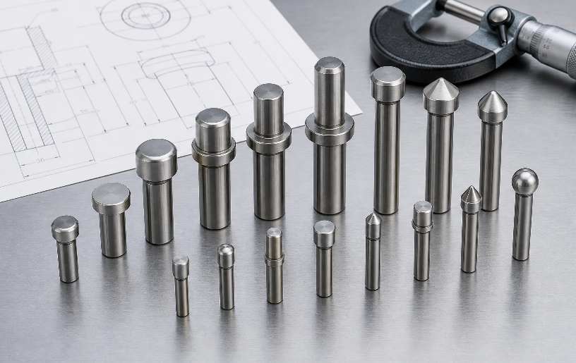
Choosing a KCF guide pin well comes down to matching four things to your application, and these map directly to what we offer as a manufacturer:
Custom dimensions and head shape to drawing. Because most fixtures are bespoke, the diameter, length, and tip or head geometry of the pin often need to be made to a specific drawing rather than pulled from a catalog. Custom machining to drawing is the core of what we do for non-standard fixtures.
A choice of insulation layer thickness. As covered above, layer thickness is a performance parameter. Offering different thicknesses lets the pin be matched to the duty cycle — heavier wear environments justify a more robust layer.
Standard sizes for fast delivery. For the common cases, stocked standard specifications ship quickly. Not every application needs a custom part, and when a standard size fits, fast availability matters more than bespoke geometry.
Help selecting the right pin for your conditions. When a customer is unsure which specification suits their line, describing the application — fastener type, cycle rate, fixture layout — lets us recommend a pin rather than leaving the choice to guesswork. This selection help is often the difference between a pin that lasts and one that disappoints.
The thread running through all four: a KCF guide pin is specified correctly when its dimensions fit your fixture, its insulation layer matches your duty cycle, and its geometry suits your fastener. Get those right and the install/maintenance discipline above does the rest.
A practical way to approach a first order or a re-specification: gather the three inputs that determine all four choices before you ask for a quote. First, the fixture interface — the seat dimension and tolerance the pin installs into, ideally from the fixture drawing rather than a measured guess off a worn pin. Second, the fastener — its type and size, since the pin’s head or tip geometry has to suit the nut, bolt, or stud it positions. Third, the duty — the cycle rate and what you weld, which drives the insulation layer thickness. With those three in hand, every one of the four specification choices follows logically, and the back-and-forth that otherwise stretches a custom order over several emails collapses into a single clear conversation. Buyers who arrive with these details get a better pin faster; buyers who order from a part number alone are the ones most likely to end up in the install and maintenance failure modes above.
A Quick KCF Guide Pin Reference Checklist
For your maintenance file, the whole article compressed:
- Function: locates the fastener without conducting current — the insulation layer is the working surface.
- Application fit: best for nut, bolt/stud, projection, and multi-fastener locating.
- Life signals: positioning off, insulation failure, visible wear — all reactive; planned weld-count replacement is the better practice.
- Install right: appropriate seating force, correct size/tolerance, verified coaxial alignment.
- Maintain right: gentle cleaning only, regular inspection of accuracy and surface.
- Specify right: dimensions to fixture, insulation thickness to duty cycle, geometry to fastener type and size.
Final Thoughts on Getting the Most From a KCF Guide Pin
A KCF guide pin rewards being understood. Its whole value lives in a micron-thin insulating surface, which means the part is easy to specify well, easy to install badly, and easy to kill early through a careless clean or a forced installation. The customers who get long, predictable life from these pins are not using a different product — they are matching the pin to the fixture, protecting the surface, and replacing on a schedule instead of waiting for a failure. None of that requires special equipment or expertise; it requires only treating a precision part as the precision part it is.
If you are specifying KCF guide pins for a new fixture or trying to understand why your current pins are not lasting, send us your fixture drawing, fastener type, and cycle rate. With those three details we can recommend a dimension, an insulation layer thickness, and a realistic life expectation — and that is a far better starting point than a catalog part number chosen in the dark. Whether you end up ordering a standard size or a fully custom part, the conversation that starts from your actual fixture is the one that ends with a pin that lasts.

About the Author Written by Kara, CEO and Lead Production Expert at Spot Welding Parts. With 26 years of front-line experience in industrial manufacturing, Kara oversees the engineering and machining of precision resistance welding consumables. She works directly with global automotive tier-1 suppliers and sheet metal fabricators to optimize electrode life, resolve stray current issues, and build reliable custom KCF tooling.
Share This Article
Latest Articles
October 19, 2026
October 19, 2026
October 19, 2026
October 19, 2026
October 19, 2026

October 19, 2026
October 19, 2026
October 19, 2026