What Is KCF Alloy? The Insulated Material Behind Reliable Nut & Bolt Welding

When a customer first contacts our factory asking for “the special pins that don’t stick during nut welding,” they are almost always describing KCF alloy without knowing its name. After years of machining KCF rods, guide pins, and sleeves for automotive body shops and appliance plants, we have learned that this single material quietly solves a problem most resistance welding operations struggle with for years: shunting current, stray welds, and parts that seize to the fixture.
This guide explains what the material actually is, why its insulating surface layer matters more than its raw hardness, and where it genuinely outperforms ordinary copper electrode material. We will also be honest about its limits, because a material that is right for guide pins is not always the right choice for a conductive electrode tip. By the end, you should be able to tell whether this is the right specification for your line — and how to avoid the handful of mistakes that cause nearly every field failure we see.
What Is KCF Alloy, Exactly?
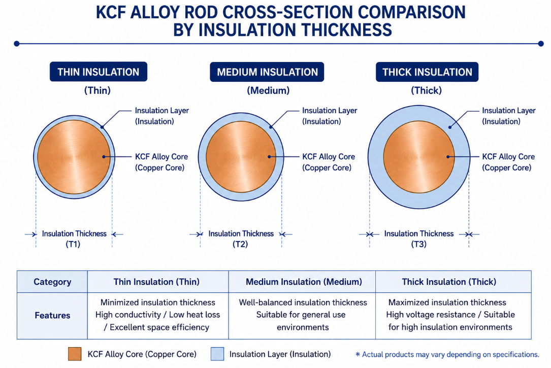
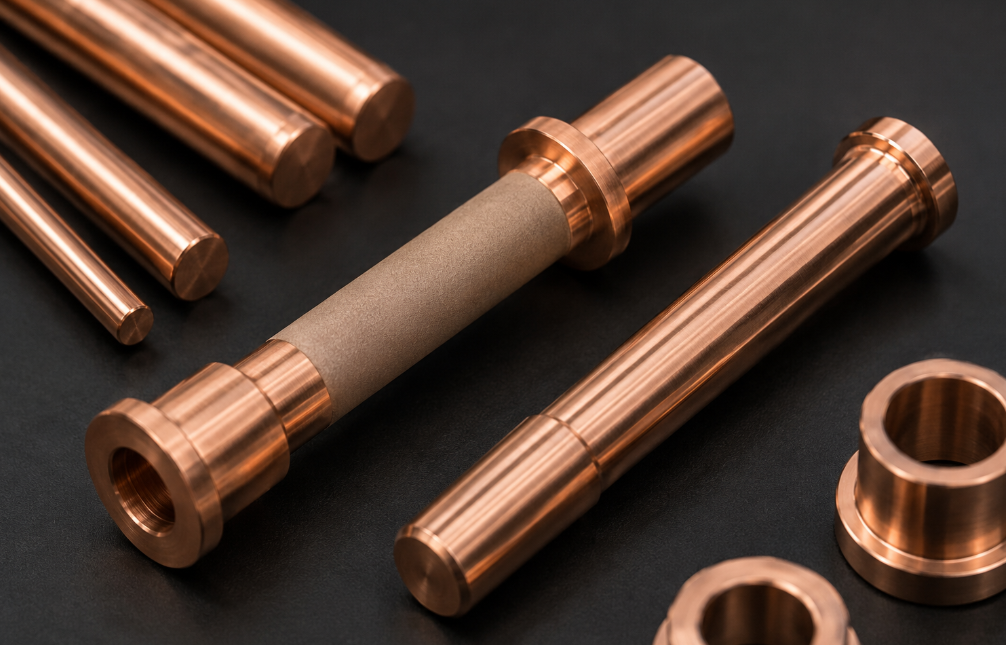
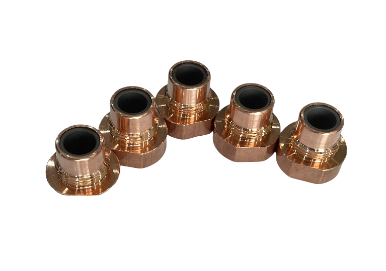
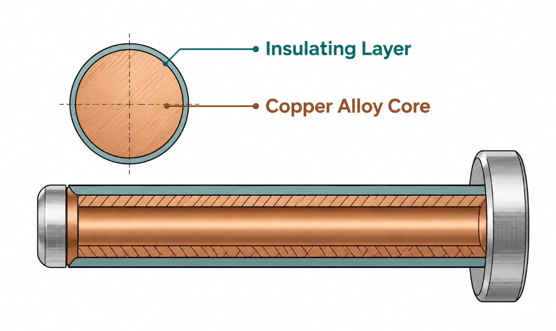
It is a copper-based composite material engineered specifically for resistance welding components that need to locate and guide without becoming part of the conductive path. The defining feature is not the base metal but the dense, ceramic-like insulating layer that forms on the surface through a controlled heat-treatment process. On the rods and pins we produce, that layer typically measures 8–15 μm thick, and it is this skin — not the copper underneath — that does the real work.
People often assume it is just another grade of copper alloy, and during price comparison they look only at the per-piece cost. This is the single most common misunderstanding we encounter. A plain copper or CuCrZr bar of the same diameter will always be cheaper, because it is missing the very thing that defines this product: a hard, electrically insulating, wear-resistant surface that lets a pin sit inside a live welding zone without drawing current through itself.
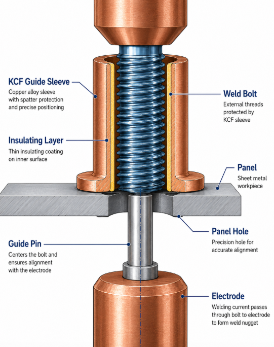
In a nut welding or bolt (stud) welding setup, you do not want the locating pin to conduct. If it does, current shunts through the pin instead of concentrating at the intended weld interface, and you get weak welds, expulsion, or the pin welding itself to the workpiece. The insulating layer is what prevents that, while the hardened body resists the constant mechanical wear of parts sliding over it thousands of times per shift. That dual behavior — insulate on the outside, stay dimensionally stable on the inside — is the whole reason the material exists as its own category rather than being lumped in with ordinary electrode copper.
Why KCF Alloy Has Two Jobs in One Part
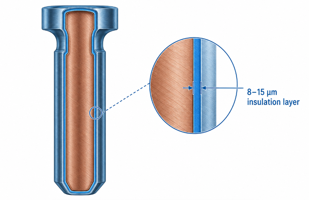
Think of the material as having two jobs handled by two different parts of the same component:
- The core provides structural strength and dimensional stability so the pin holds tight tolerances inside a fixture, even as temperature cycles up and down through a production shift.
- The surface layer provides high insulation resistance and abrasion resistance, so it neither conducts stray current nor wears away under repeated contact.
Remove or damage that surface layer, and the part stops being what it is supposed to be — a point we return to below, because it is the root of most field complaints. This is also why two pins that look identical and measure identical on a caliper can perform completely differently: the caliper measures the body, but the performance lives in the micron-thin layer the caliper cannot feel.
How Is KCF Alloy Different From Standard Copper Electrode Material?
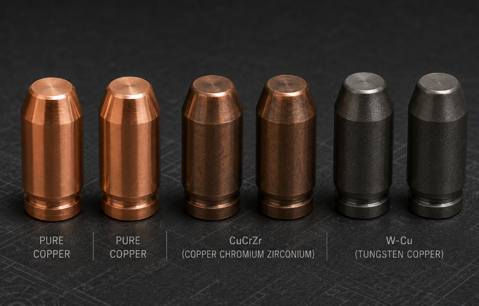
The resistance welding industry classifies conductive electrode materials under the RWMA (Resistance Welding Manufacturers Alliance) system, now maintained as a committee of the American Welding Society. Under that system, materials like CuCr and CuCrZr fall into Group A, Class 2 — the general-purpose conductive electrodes used for the actual welding tips. According to AWS guidance, Class 2 copper is the standard choice for most spot welding because it balances conductivity and strength. You can read the AWS overview of electrode material selection in their Welding Digest electrode selection guide.
This material plays a fundamentally different role. It is not trying to conduct current efficiently — it is trying not to. This is why comparing it to a CuCrZr electrode on the basis of conductivity misses the point entirely. They are teammates on the same welding station, not competitors: one carries the current and forms the weld, the other holds the workpiece in exactly the right place while staying electrically out of the way.
The table below summarizes how the material compares to common conductive electrode materials in the roles each is built for.
| Property | KCF Alloy | CuCrZr (RWMA Class 2) | Pure Copper (RWMA Class 1) |
|---|---|---|---|
| Primary role | Locating / guiding (non-conductive) | Conductive welding tip | High-conductivity tip (aluminium, etc.) |
| Surface insulation | Yes — 8–15 μm insulating layer | No | No |
| Electrical conductivity | Intentionally low at surface | Moderate–high | Highest |
| Surface hardness / wear resistance | High | Moderate | Low |
| High-temperature oxidation resistance | High | Moderate | Low |
| Typical use | Guide pins, guide sleeves, locating pins | Spot/projection electrode tips | Aluminium & high-conductivity sheet |
The key takeaway: a buyer who uses it as if it were an ordinary conductive electrode — without distinguishing the locating role from the conducting role — is using the wrong tool for the job, and will not see the benefit they paid for. We have had customers return parts as “not working” when the real issue was that they had installed an insulating locating pin where a conductive tip belonged. The material was fine; the role assignment was not.
KCF Alloy Versus Solid Ceramic Pins
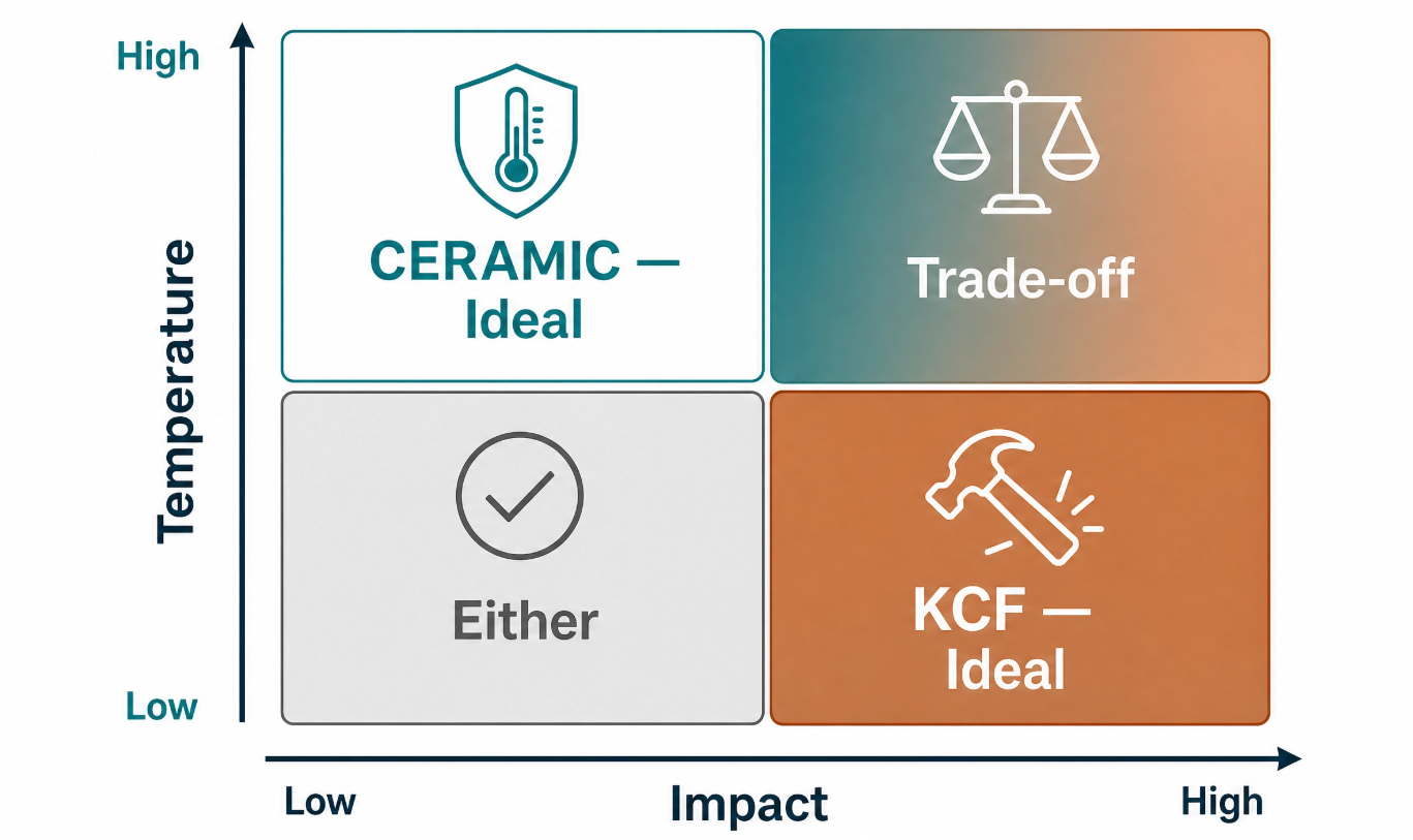
Buyers evaluating non-conductive locating parts also weigh it against solid ceramic pins. Ceramic offers excellent insulation and heat resistance, but it is brittle and chips under impact, and it cannot be machined as freely. The metal core of a KCF part gives it toughness that solid ceramic lacks, which matters on lines where pins take mechanical knocks. We cover that trade-off in depth elsewhere, but the short version is that ceramic wins on pure insulation and KCF wins on durability and machinability — which is why high-impact, high-cycle lines tend to favor the latter.
Where Is KCF Alloy Actually Used?
In our own order book, the rods and finished pins flow into three main destinations, and understanding them helps clarify when this material is the right specification.
KCF Alloy in Automotive Body Welding
The largest share of our orders goes into automotive assembly — specifically nut and bolt (stud) welding on car body panels. Modern vehicle bodies carry dozens of weld nuts and weld studs for mounting brackets, seats, and trim. Each of those joints relies on a locating pin to position the nut or stud precisely before the weld fires. Because these lines run at high volume and tight cycle times, the locating pin has to survive enormous repeated contact while never shunting current. This is the textbook application, and it is why KCF guide pins are found on assembly lines feeding major automakers worldwide. When an automotive customer reports stable weld quality over hundreds of thousands of cycles, the locating components are usually doing their job invisibly — which is exactly the goal.
KCF Alloy in General Metal Fabrication
The second stream is general metalworking and sheet metal fabrication — shops that weld nuts or studs onto enclosures, frames, and assemblies across many industries. These customers often have more varied part geometries, which is where customization matters: a guide pin that fits one fixture perfectly may be useless in another. We frequently machine the rods to bespoke diameters and lengths from a customer’s drawing for exactly this reason. Fabrication shops also tend to run mixed batches, so a pin that holds tolerance across different nut sizes earns its keep by reducing changeover fiddling.
KCF Alloy Rod Stock for Secondary Processors
The third stream is unusual but important: machine shops that buy KCF alloy rod stock and turn it into finished guide pins and sleeves themselves. These are sophisticated buyers who want control over their own part geometry, but they introduce a specific risk we will address next — because the way a part is machined determines whether the insulating layer survives. Selling rod stock to this group taught us more about the material’s failure modes than any lab test, because we see exactly what happens when the surface layer is treated as ordinary metal.
The Most Common KCF Alloy Mistakes (From Real Customer Cases)
Honesty about what goes wrong is what separates a real manufacturer from a catalog reseller. Here are the recurring problems we see, drawn directly from customer support cases.
Mistake 1: Treating KCF Alloy as Ordinary Copper During Price Comparison
As noted earlier, comparing it to plain copper on unit price alone is comparing two different products. The buyers who learn this the hard way are usually the ones who switched to a cheaper “equivalent,” then saw stray welds and stuck pins return within weeks. The insulating layer is the product. Pay for it, or you are not buying the real product at all — you are buying a copper bar that happens to be the same shape.
Mistake 2: Ignoring the KCF Alloy Insulation Layer Thickness
Some buyers select a part purely on diameter and length, without specifying or even asking about the insulation layer thickness. But that 8–15 μm layer is a performance parameter, not a cosmetic finish. Too thin for the duty cycle, and insulation can break down sooner under wear; matched correctly to the application, it lasts. The right thickness is something worth discussing before ordering, not after a failure — and a manufacturer who cannot tell you the layer thickness is a warning sign in itself.
Mistake 3: Using KCF Alloy in the Wrong Role
We occasionally see these parts installed where a conductive electrode belongs, or vice versa, because the operation did not clearly separate “the part that locates” from “the part that conducts.” This material is for locating and guiding. If you need current to flow through the component, you need a conductive electrode material, not an insulated one. Mapping out which components conduct and which only locate, before ordering, prevents this entirely.
Mistake 4: Destroying the KCF Alloy Insulating Layer During Machining
This is the most damaging mistake, and it mostly affects the secondary processors mentioned above. When a shop turns, grinds, or re-faces a rod aggressively, it can cut straight through the 8–15 μm insulating layer and expose the conductive core — without realizing it. The part looks fine. It measures correct. But its insulation performance is gone, and the welding problems that follow get blamed on “bad material” when the real cause was the machining. If you machine this material in-house, you must protect the functional surfaces and verify insulation afterward with a simple resistance check before the parts ever reach the line.
What Goes Wrong in the Field: KCF Alloy After-Sales Reality
To keep this guide genuinely useful rather than promotional, here is a candid look at the after-sales issues that actually arise — and what causes them.
| Reported Issue | Usual Root Cause | Who Can Prevent It |
|---|---|---|
| Insulating layer wears or flakes early | Layer thickness mismatched to duty cycle, or excessive abrasive contact | Manufacturer + buyer (spec selection) |
| Dimensions don’t match the customer’s fixture | Tolerance not aligned with the actual fixture during ordering | Manufacturer + buyer (drawing review) |
| Insulation performance drops after customer machining | Insulating layer cut through during secondary processing | Buyer (machining method) |
| Surface damage on arrival | Impact or abrasion during transport and handling | Manufacturer (packaging) |
A few honest observations from these cases:
Tolerance mismatch is a communication problem, not a metallurgy problem. Most “wrong size” complaints trace back to a fixture dimension that was never shared at the quoting stage. When we get the actual fixture drawing up front, this category of complaint nearly disappears. It costs nothing to send a drawing and saves a reorder.
Post-machining insulation loss is almost always preventable — see Mistake 4. We now flag this risk explicitly with any customer buying rod stock for in-house finishing, and we recommend a quick continuity check on finished pins before they go into service.
Transport damage is on us as the maker. A 12 μm surface layer does not forgive being thrown into a box loose, so protective packaging is part of the product, not an afterthought. We learned this from early shipments and changed how we pack.
The upside of being this specific: when a buyer understands these four failure modes before ordering, the actual field failure rate is very low. The material itself is stable and consistent when specified and handled correctly — the variability is almost always introduced after it leaves the factory.
It is worth dwelling on why these four issues, and not metallurgy, dominate the complaint log. A locating pin is a deceptively simple-looking part, so buyers reasonably treat it like a commodity fastener: pick a diameter, pick a length, place the order. But the surface layer turns that simple part into a precision item whose performance depends on three things the drawing alone never captures — the duty cycle it will face, the way it will be machined, and the way it will be handled before installation. None of those live on a dimensional print. That is the real lesson of the support log: the part is only half-specified by its geometry, and the missing half is the conversation about how it will actually be used. A five-minute exchange about cycle counts and fixture conditions at the quoting stage routinely prevents a complaint that would otherwise surface weeks later on the line.
Why Choose KCF Alloy? The Three Advantages That Matter
Set against its limits, here is where the material genuinely earns its place.
KCF Alloy Hardness and Wear Resistance for Long Service Life
A locating pin in a high-volume nut welding line endures relentless mechanical contact. The hardened body and hard surface layer resist that wear far better than soft copper, which translates directly into longer service intervals and less line downtime spent swapping pins. For a high-cycle automotive line, that longevity is the entire economic argument: the unit cost is higher, but the cost per thousand cycles is lower, and the unplanned stoppages are fewer.
Full KCF Alloy Customization to Drawing
Because so many fixtures are bespoke, the ability to produce rods, pins, and sleeves to any required diameter, length, and tolerance from a customer drawing is often the deciding factor. Standard sizes serve the common cases, but the value of a direct manufacturer is making the non-standard part that the fixture actually needs — and matching the insulation spec to the duty cycle at the same time. A reseller can only sell you what is in the catalog; a factory can make what your fixture demands.
KCF Alloy High-Temperature and Oxidation Resistance for Continuous Production
Resistance welding zones are hot and oxidizing environments. The surface layer is formed through high-temperature heat treatment, which is precisely why it holds up under the thermal and oxidative stress of continuous production. A pin that resists oxidation keeps its insulating and dimensional properties stable shift after shift, rather than degrading after a few hours of running. On a line that runs three shifts a day, that stability is what keeps weld quality consistent from the first part of the morning to the last part of the night.
Is KCF Alloy Right for Your Application? A Quick Decision Guide
Use this short checklist:
- Do you need a component to position a nut, bolt, or stud without conducting current? → this material is likely correct.
- Do you need current to flow through the component to make the weld? → You need a conductive electrode (CuCrZr / RWMA Class 2), not an insulated locating part.
- Are you running high volume with tight cycle times? → The wear resistance pays for itself.
- Will you machine the part yourself? → Choose the material, but plan to protect and verify the insulating layer.
- Is your fixture non-standard? → A custom-machined part to your drawing is the right path.
For deeper reference on how electrode and component materials are standardized across the industry, the AWS maintains the RWMA Resistance Welding Manual and related J1.3 material specifications, which is the authoritative source for material classes and their intended applications.
How to Specify the Right KCF Alloy Part on Your First Order
If the checklist points you toward an insulated locating component, a little preparation makes the first order go smoothly and keeps it out of the four failure categories above. Start by pulling the fixture drawing and noting not just the pin diameter and length but the seating tolerance and any clearance the nut or stud needs to drop in cleanly. Record the realistic cycle count per shift, because that number drives the layer thickness recommendation more than anything else. Note whether you will install the part as supplied or machine it further in-house, and flag it if so. Finally, describe the welding environment briefly — current range, whether the line runs continuously, and whether you weld coated or galvanized stock, since zinc and coatings change wear behavior. With those five inputs, a manufacturer can recommend a specification with confidence rather than guesswork, and you avoid the most common reason first orders disappoint: a part that was technically made to print but never matched to the process it had to survive.
Final Thoughts on Choosing KCF Alloy
KCF alloy is not a premium version of copper — it is a different material built for a different job. Its insulating surface layer is the whole point, and nearly every success or failure traces back to whether that layer was specified correctly, machined carefully, and protected in transit. Get those three things right, and the material delivers exactly what high-volume nut and bolt welding needs: precise location, long life, and clean welds free of shunting.
If you are evaluating this material for a new line or trying to solve a stray-weld problem on an existing one, the most useful first step is to share your fixture drawing and duty cycle. That single conversation prevents most of the issues described above — and it is the difference between buying a part number and buying a part that actually fits your process.

About the Author Written by Kara, CEO and Lead Production Expert at Spot Welding Parts. With 26 years of front-line experience in industrial manufacturing, Kara oversees the engineering and machining of precision resistance welding consumables. She works directly with global automotive tier-1 suppliers and sheet metal fabricators to optimize electrode life, resolve stray current issues, and build reliable custom KCF tooling.
Share This Article
Latest Articles
October 19, 2026
October 19, 2026
October 19, 2026
October 19, 2026
October 19, 2026

October 19, 2026
October 19, 2026
October 19, 2026