KCF Alloy Rod Specifications: Diameter, Insulation Layer Thickness & Tolerances

When a customer is ready to order KCF alloy rod, the conversation shifts from “what is this material” to “what exactly do I need” — and that is where orders go right or wrong. A diameter chosen without reference to the actual fixture, a tolerance set too tight or too loose, an insulation layer thickness picked by default rather than by duty cycle: each is a specification decision that determines whether the part performs or disappoints. This is the specification reference we wish every buyer had in front of them before sending a drawing.
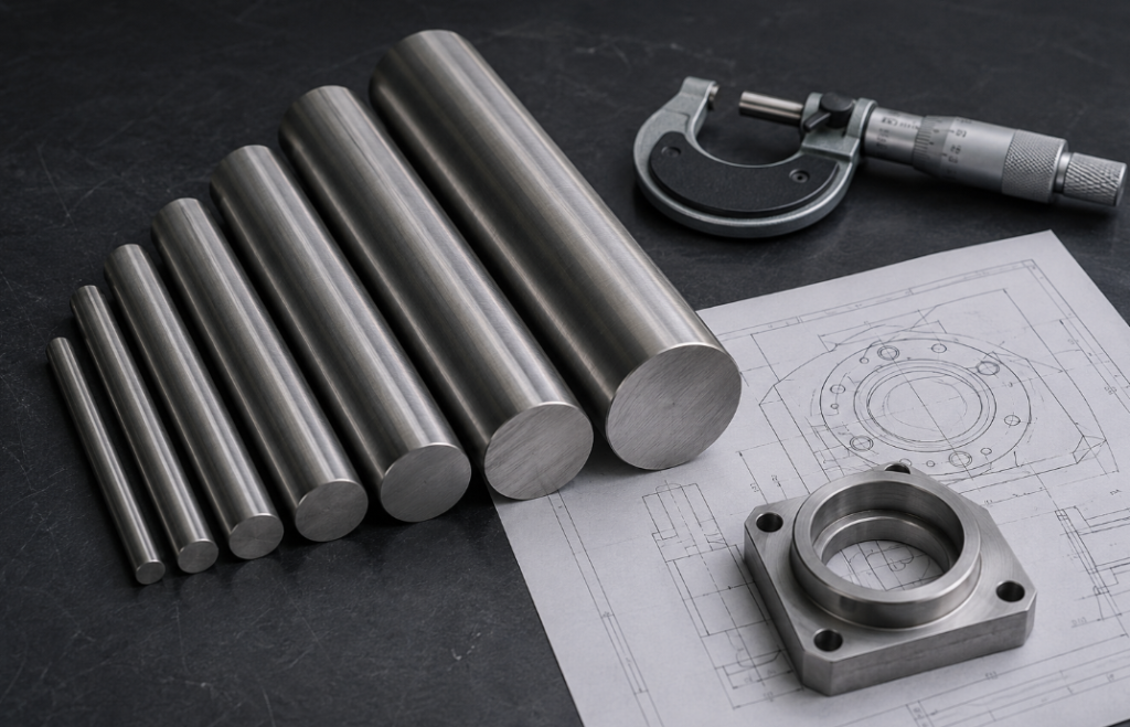
We make KCF alloy rod in standard diameters and to custom drawings, so we see the full range of how these parts get specified — and mis-specified. This guide walks through every specification that matters: diameter and the standard sizes we stock, insulation layer thickness and why thicker is not always better, dimensional tolerance and the fit it must achieve, length and head geometry, and the documentation a serious order should include. Three reference tables summarize the key trade-offs.
KCF Alloy Rod Diameter: Standard Sizes and Custom Options
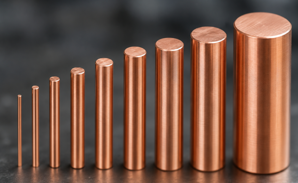
Diameter is the first specification, and for many applications it can come from stock. We keep KCF alloy rod in a set of common standard diameters — typically values such as 3, 4, 5, 6, 8, and 10 mm — that cover the majority of nut and bolt welding fixtures. When your application fits a standard size, ordering from stock means faster delivery and no tooling lead time.
But the standard sizes are a convenience, not a constraint. Because KCF alloy rod is a machinable metal-cored material, we routinely turn it to non-standard diameters from a customer drawing. If your fixture needs 5.5 mm, or 7 mm, or any intermediate value, that is a machining job, not a special-order obstacle. The decision rule is simple: if a standard diameter matches your fixture hole and fastener, use it for speed; if it does not, specify the exact diameter you need rather than forcing the nearest stock size, because a diameter that is “close” is the beginning of the tolerance problems described below.
How to Choose KCF Alloy Rod Diameter From Your Fixture
The diameter you need is not an independent choice — it is dictated by the nut, bolt, or stud you locate and the fixture hole the pin sits in. The pin’s diameter must match the fastener’s hole closely enough to locate it accurately, while fitting the fixture seat correctly. This is why the most reliable way to specify diameter is to work from the actual fixture and the actual fastener, not from a catalog number remembered from a previous job. We routinely help customers select the right diameter by working back from their nut hole and fixture dimensions — that backward derivation is more dependable than a forward guess.
A subtlety worth flagging: the diameter that locates the fastener and the diameter that seats in the fixture are sometimes two different dimensions on the same part. A pin can have a locating portion sized to the nut hole and a mounting portion sized to the fixture seat, with a shoulder or step between them. When that is the case, both diameters need specifying, each with its own tolerance, and conflating them is a common source of a part that fits the fixture but locates the nut poorly, or vice versa. The component-level mechanics of how these pins seat and locate are covered in our guide to KCF guide pins; here the point is simply that “diameter” may not be a single number, and a good drawing makes every diameter on the part explicit.
KCF Alloy Rod Insulation Layer Thickness: Why More Is Not Always Better
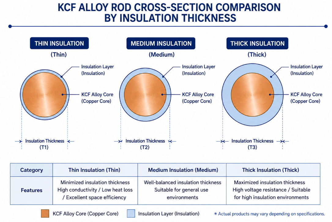
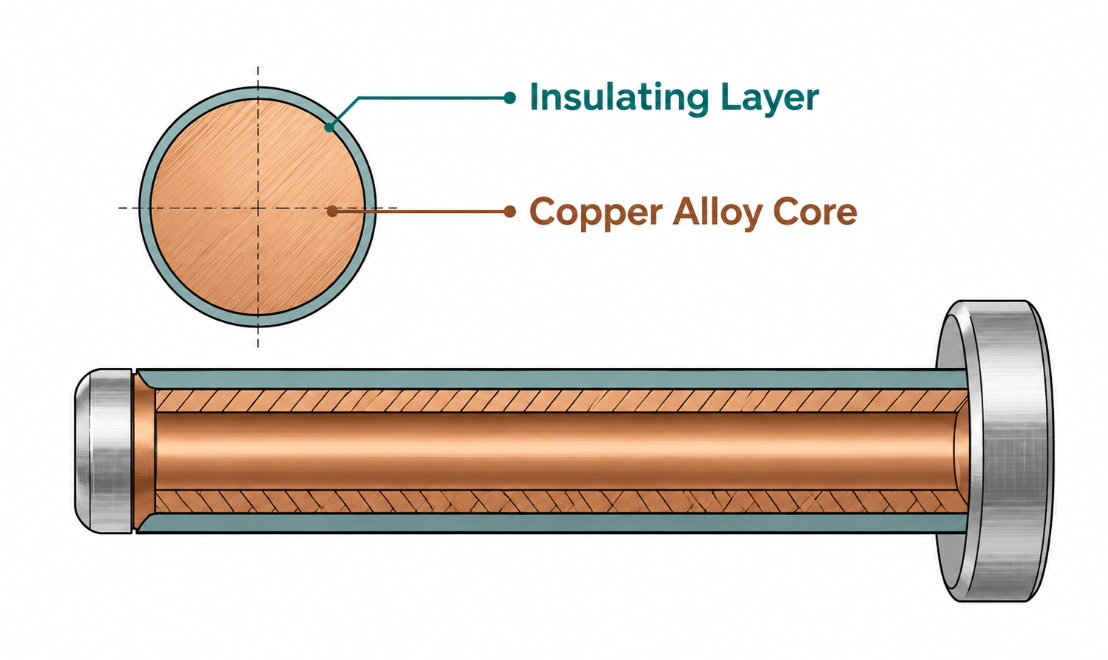
The insulation layer is what makes KCF alloy rod what it is, and its thickness is a genuine performance specification — covered in principle in our article on what KCF alloy is. On our rod, the standard insulation layer falls in the 8–15 μm range, and we can supply different thicknesses matched to the application.
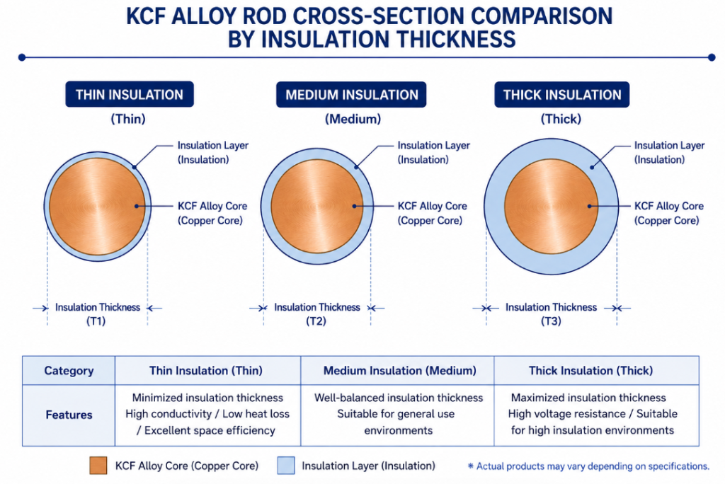
The intuition that “thicker insulation is always safer” is wrong, and this matters for specification. Here is the real relationship:
Thicker layers suit heavier duty. For high-frequency or heavy-duty applications where the surface endures more wear per shift, a thicker insulation layer provides more material to wear through before electrical isolation degrades. Heavy-cycle automotive lines justify the thicker end of the range.
But thickness has an upper limit. Beyond a certain point, a thicker insulation layer becomes counterproductive — an excessively thick layer can introduce its own problems rather than adding benefit. The insulation is not a coating where more is always better; it is an engineered surface with an optimal range. This is why we do not simply maximize thickness on every pin.
Why does more eventually become worse rather than merely unnecessary? A surface layer is not free of trade-offs as it grows: its mechanical behavior, its adhesion to the core, and its dimensional contribution all shift with thickness, and past the engineered window those shifts start to work against the part rather than for it. The practical consequence for a buyer is that “give me the maximum insulation you can” is not a conservative, safe request — it can be an actively worse specification than the correct mid-range value. The safe request is not “maximum” but “matched,” and a supplier who understands the material will push back on a maximum-thickness request for a light-duty application rather than simply taking the order. That pushback is a sign of competence, not unhelpfulness.
The right thickness is matched, not maximized. The correct specification pairs layer thickness to the duty cycle: lighter duty does not need the thickest layer, heavy duty justifies it, and there is a sensible ceiling above which more thickness stops helping. Choosing within that window is part of specifying the rod correctly, and it is a decision worth discussing rather than defaulting.
The table below summarizes how insulation layer thickness maps to application.
Table 1 — KCF Alloy Rod Insulation Layer Thickness by Application
| Application Duty | Suggested Layer Approach | Rationale |
|---|---|---|
| Light / low-cycle | Lower end of the 8–15 μm range | Adequate wear margin; no benefit from maximum thickness |
| General production | Mid 8–15 μm range | Balanced wear life for typical duty |
| Heavy / high-frequency | Upper end of the range | More material to wear through before isolation degrades |
| Above the practical ceiling | Not recommended | Excessive thickness introduces its own problems |
The takeaway for a buyer: do not ask for “the thickest available.” Ask for the thickness matched to how hard your line runs, and treat any supplier who only offers one thickness — or who claims more is always better — with appropriate caution.
KCF Alloy Rod Tolerance: The Specification That Matters Most
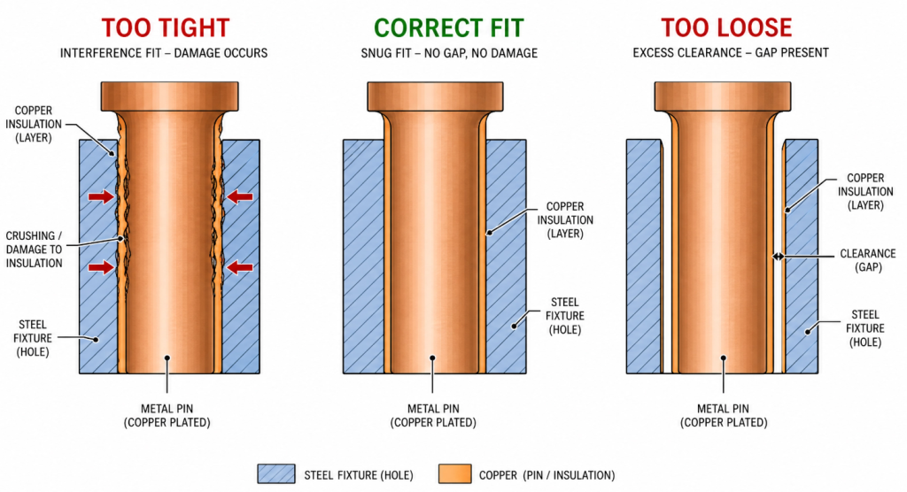
If diameter is the first specification and insulation thickness the most distinctive, tolerance is the most consequential — the one where small errors cause the largest field problems. Diameter tolerance governs the fit between the pin and the fixture, and that fit has a narrow window between two failure modes.
The international system for specifying exactly this kind of pin-to-hole fit is ISO 286, which defines tolerance grades and fit classes for mating parts; toolmakers use it specifically for precision fits on guide pins, dowels, and bushings. Understanding the principle it encodes is the key to specifying the part correctly: the same nominal diameter can produce a loose clearance fit or a tight interference fit depending entirely on the tolerance applied, and for a locating pin you need to land deliberately in the right zone.
It is worth dwelling on that principle, because it is where intuition most often fails buyers. A nominal diameter — say, “6 mm” — feels like a complete specification, but it is only the midpoint of a range. The tolerance defines how far above and below that midpoint the actual part may fall, and a few hundredths of a millimetre in either direction is the entire difference between a pin that drops into the fixture with a precise sliding fit and one that either rattles or has to be pressed. ISO 286 captures this with a letter-and-number code: the letter sets where the tolerance band sits relative to nominal, the number sets how wide the band is. The reason the standard matters here is not that you must quote ISO codes on your order — it is that the standard proves, in formal engineering terms, that diameter without tolerance is an incomplete specification. Two pins both honestly labelled “6 mm” can behave completely differently in the same fixture, and only the tolerance distinguishes them.
The two failure modes define the window:
Tolerance too tight → insulation damage on installation. If the diameter tolerance makes the pin too large for the fixture seat, installation requires forcing the pin in. That press-in force can crush or breach the 8–15 μm insulation layer at the contact points, destroying the pin’s electrical function before it ever runs a weld. A pin that has to be hammered home is a pin whose insulation is already at risk.
Tolerance too loose → poor location and wobble. If the tolerance makes the pin too small, it sits loose in the fixture. Location accuracy suffers, the pin can wobble or shift, the nut sits imprecisely, and premature wear follows from the movement. The weld quality that depends on accurate location degrades. A loose pin is also a sticking risk: imprecise location feeds the expulsion and mislocation problems detailed in our article on why nut welding electrodes stick, so a tolerance error does not stay contained to “fit” — it propagates into weld quality and consumable life.
The tolerance must match the customer’s fixture hole. This is the single most important point in the entire specification. The correct diameter tolerance is the one that produces the right fit in your fixture — not a generic tolerance, but one referenced to your actual hole dimension. This is precisely why we ask for fixture details rather than only a nominal diameter, and why a custom tolerance referenced to your fixture is often the right specification rather than a stock tolerance band.
Table 2 — KCF Alloy Rod Tolerance: Failure Modes and Fit
| Tolerance Condition | Resulting Fit | Consequence |
|---|---|---|
| Too tight (pin oversized to seat) | Interference / press fit | Insulation layer crushed or breached on installation |
| Correct (matched to fixture hole) | Intended locating fit | Accurate location, insulation protected, full service life |
| Too loose (pin undersized to seat) | Excess clearance | Wobble, poor location, premature wear, weld quality drift |
The lesson reads directly off the table: the middle row is the entire goal, and you cannot hit it without referencing the actual fixture. A nominal diameter alone does not specify a pin; a nominal diameter plus a tolerance referenced to the fixture does.
KCF Alloy Rod Length and Head Geometry
Two further specifications round out the order. Both are application-driven rather than catalog-fixed.
Length. The pin or rod length must suit the fixture and the fastener stack it locates. We machine KCF alloy rod to the length the application requires; for customers buying rod stock to finish in-house, length is cut to their specification. Length is rarely the source of trouble on its own, but it must be correct for the pin to seat fully in the fixture and protrude by the right amount for the fastener to drop on and locate — too short and the fastener is not captured, too long and it can foul the closing electrode.
Head and tip geometry. The shape of the pin’s working end — the tip or head that the fastener seats against — is determined by the fastener type and how it must be located. Different nuts and studs call for different head geometries, and machining the correct shape from a drawing is part of producing a pin that locates cleanly rather than approximately. This is one of the clearest reasons KCF’s machinability matters: a metal-cored material can be turned to whatever head form the fastener needs.
A note on surface finish, since it interacts with everything above: the surface texture of a machined pin is itself a specification, governed internationally by ISO 1302 surface finish standards. Surface condition influences wear behavior and how cleanly a fastener locates and releases, which is part of why machining quality — not just nominal dimensions — separates a pin that lasts from one that does not.
Documentation: What a Complete KCF Alloy Rod Order Includes
A specification is not complete when the dimensions are set — it is complete when the order can be verified. For KCF alloy rod, a serious order should include or be backed by proper documentation, and this is a place where supplier quality shows.
Material certification and hardness reports. Because KCF alloy rod is a copper-based engineered material, its properties — including hardness, which reflects the material condition — can be documented. We provide material certification and hardness reporting, which lets a buyer verify they received the specified material rather than taking it on faith. The base copper alloy properties that underlie these materials are well characterized in references such as the Copper Development Association’s technical resources, and a maker working with certified material can document what they supply.
Why documentation matters for this part specifically. A KCF pin’s value lives in properties you cannot see — the insulation layer’s integrity, the material’s condition. Documentation is how those invisible properties become verifiable. A supplier who can provide material certification and hardness data is demonstrating control over the product; one who cannot is asking for trust the part’s appearance cannot justify.
The hardness report deserves particular attention because it is a window into something no dimension reveals: the material’s condition. Hardness reflects whether a copper-based material has been properly processed, and a hardness value that falls outside the expected band is an early warning that something in the material’s preparation was wrong — even when the chemistry and the dimensions are correct. For a buyer, this makes the hardness report a cheap and powerful verification: it costs the supplier little to provide, and it lets you confirm not just that the part is the right size, but that the material behind the part is what it should be. Insisting on it early — as part of the order, not as a reaction to a failure — is one of the simplest disciplines that separates buyers who get consistent parts from buyers who get surprises.

Table 3 — Complete KCF Alloy Rod Specification Checklist
| Specification | What to Define | How We Support It |
|---|---|---|
| Diameter | Nominal size from fixture & fastener | Standard sizes (3–10 mm) or custom to drawing |
| Insulation layer thickness | Matched to duty cycle, within 8–15 μm window | Multiple thicknesses; guidance on matching |
| Diameter tolerance | Referenced to your fixture hole | Custom tolerance to fixture, not generic band |
| Length | Suited to fixture and fastener stack | Machined to specification |
| Head / tip geometry | Determined by fastener type | Machined to drawing |
| Surface finish | Appropriate for wear and location | Controlled machining quality |
| Documentation | Material cert + hardness report | Provided with order |
This table is the whole article in one single place: seven specifications, each defined against your application rather than guessed, and each something a capable manufacturer supports rather than improvises.
How to Specify KCF Alloy Rod: A Practical Order Sequence
Putting it together, here is the sequence that produces a correct order the first time:
- Start from the fixture and fastener. Measure the actual fixture hole and the nut, bolt, or stud being located. These dictate diameter and tolerance — the two specifications that matter most.
- Set diameter. Use a standard size if one matches; specify exact custom diameter if not. Do not force the nearest stock size onto a fixture it does not fit.
- Reference the tolerance to the fixture hole. This is the critical step — the tolerance must produce the right fit in your actual seat, landing between the too-tight and too-loose failure modes.
- Match insulation thickness to duty cycle. Within the 8–15 μm window, lighter duty toward the lower end, heavy duty toward the upper, never beyond the practical ceiling.
- Define length and head geometry from the fastener and fixture stack.
- Require documentation. Material certification and hardness reporting should come with the order, not after a problem.
A buyer who arrives with the fixture hole dimension, the fastener, and the duty cycle has given a manufacturer everything needed to specify a pin that fits and lasts. A buyer who arrives with only a nominal diameter has given the starting point for the failure modes in Tables 1 and 2.
Final Thoughts on Specifying KCF Alloy Rod
KCF alloy rod is easy to specify well and easy to specify badly, and the difference is almost entirely about reference points. A diameter referenced to your fixture, a tolerance referenced to your hole, an insulation thickness referenced to your duty cycle, and documentation referenced to verifiable material properties — those reference points turn a part number into a part that works. Specify in the abstract, and you inherit the loose-fit wobble, the press-in insulation damage, and the mismatched layer thickness that fill our support cases.
If you are preparing a KCF alloy rod order, the most useful thing you can send is your fixture hole dimension, your fastener details, and your line’s duty cycle. From those we can recommend diameter, tolerance, insulation thickness, length, and head geometry — and back the order with material certification and hardness data. Browse our KCF alloy rods range for standard sizes, or send your fixture details and let us specify the part to your actual application rather than to a guess. The order that starts from real fixture numbers is the order that arrives as a part you can install once and forget — which, for a locating pin, is exactly the outcome worth specifying for.
Share This Article
Latest Articles
October 19, 2026
October 19, 2026

October 19, 2026
October 19, 2026
October 19, 2026

October 19, 2026
October 19, 2026
October 19, 2026